Wiring Harness.....
Moderator: Ken
Wiring Harness.....
![]() by matter396 » 31 Fri Jul, 2009 6:41 pm
by matter396 » 31 Fri Jul, 2009 6:41 pm
Mike
- matter396
- Buggy Nut
- Posts: 112
- Joined: 03 Sat Jan, 2009 12:01 pm

![]() by Aquabuggy » 31 Fri Jul, 2009 9:35 pm
by Aquabuggy » 31 Fri Jul, 2009 9:35 pm
http://www.dunebuggy.com/shop/index.mp? ... o=FEATURED
04 Aqua buggy - sold
72 Orange buggy - sold
72 Green longbody - aka Shrek http://texasmanxclub.com/bboard/viewtopic.php?t=1082
68 Manx - viewtopic.php?f=11&t=2509
-

Aquabuggy - Buggyholic
- Posts: 942
- Joined: 02 Sun Oct, 2005 10:18 am
- Location: Victoria Tx
![]() by jspbtown » 31 Fri Jul, 2009 9:48 pm
by jspbtown » 31 Fri Jul, 2009 9:48 pm
I like the way it works. I add some relays for my personal application (wipers, headlights, horn and flashers). I also make one modification as when you are done with the basic wiring you generally have two constant hot circuits left over. The mod I do makes it one constant and one keyed.
You still need lots of wire for the grounds. I run the grounds to a terminal strip which I think makes chasing ground gremlins alot easier. You also need alot of wire for most of the circuits. For an example the headlight wire is only about 6" long.
I also use the terminal strips for headlights and blinkers.
- jspbtown
- Buggyholic
- Posts: 250
- Joined: 26 Wed Dec, 2007 9:57 am
![]() by Fred » 04 Tue Aug, 2009 7:16 pm
by Fred » 04 Tue Aug, 2009 7:16 pm
- Fred
- Buggy Nut
- Posts: 120
- Joined: 05 Mon Jan, 2009 7:55 pm
- Location: Tyler TX
![]() by DannyT » 05 Wed Aug, 2009 6:59 am
by DannyT » 05 Wed Aug, 2009 6:59 am
jspbtown wrote:I too have used the dune buggy shop harness on two cars so far. I get mine off EBAY though.
I like the way it works. I add some relays for my personal application (wipers, headlights, horn and flashers). I also make one modification as when you are done with the basic wiring you generally have two constant hot circuits left over. The mod I do makes it one constant and one keyed.
You still need lots of wire for the grounds. I run the grounds to a terminal strip which I think makes chasing ground gremlins alot easier. You also need alot of wire for most of the circuits. For an example the headlight wire is only about 6" long.
I also use the terminal strips for headlights and blinkers.
Ok, help me out here. The left terminal strip......switched hot? The right terminal strip.......bulk grounds? What have you got connected to the three relays and what is routed directly to the fuse box. I really like this layout and would like to use it as a guide if possible.
- DannyT
- Buggy Nut
- Posts: 90
- Joined: 09 Mon Feb, 2009 10:59 am
- Location: Tyler, Texas
![]() by jspbtown » 05 Wed Aug, 2009 9:38 am
by jspbtown » 05 Wed Aug, 2009 9:38 am
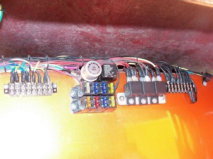
On this fuse panel 4 circuits are constant hot and 4 are switched.
Regarding the terminal strip on the right. It is all grounds.
The terminal strip on the left: If you look closely you will see some connectors on the bottom. The first 2 screws are connected, the second 2 are connected, and the last 4 are connected. The last 4 are my headlight circuit. I take the large headlight wire from the fuseblock and bring it to a relay(30 tab). From the relay (87 tab) it goes to the terminal strip. I now have 8 screws (4 upper and 4 lower) that are hot when I hit the lights. From those screws I run wires to my front marker lights, my headlight dimmer switch, my rear lights, my license plate light, and my dash lights.
The two sets of 2 screws that are connected together are for my blinkers. I run the wire that is hooked up to the flasher to my turn signal switch. Then the wire for the left signals to one set of 4 screws (2 upper & 2 lower) and my wire from the switch for the right blinkers to the other set of 4. From there I run my front turns, my rear turns, and I tap a wire for my signal indicators. I also run a wire from each set to a relay (more about that later).
For the relays: The relay on the block is used for the horn. In the picture you can see a black wire coming from behind the fuse block mounted relay. Normally that is attached to a steel firewall and provides the negative for the relay coil. Instead of drawing the negative from the steel firewall, I use the negative signal from my horn button to activate the relay. So you take the positive signal from the relay (87 tab), run it to the horn, and then ground the horn. You tap a neighboring fuse (in the back of the panel...real easy) to supply power for the relay coil, and then the horn button activates it through that little grounding wire thats already on the panel.
Another relay is for the headlights as described above. With this set up you only have all the lights on or all the lights off. There is no option of running the parking lights seperate. It can be done, but requires a different switch other than the simple toggle I like to use.
Another relay if for the wipers. I bring power from the wiper fuse to the 30 tab on the relay. I ground the 85 tab, bring power from my switch to the 86 tab, bring power to the low speed tab on the wiper motor from the 87 tab, and run a wire from the 87a tab on the relay to the auto park on the wiper motor. With this set up you only have one speed, it will auto park, and I get to use a simple toggle switch which I like because you can use the same style switch for everything.
The last relay is for the flashers. I again use the same style toggle switch. Instead of a SPDT relay I use a DPST relay. The "dual pole" allows you to keep the turn signal circuits separate. For wiring I bring power to the relay (86 tab)via the switch, ground the coil (85 tab), and for the power (30 tab) I tap into the existing flasher (although you can add a separate flasher if you wish) and run a wire from the two output tabs on the relay to the two blinker circuits on the terminal switch. So when you flip the toggle, the relay coil energizes which makes the connection between the flasher and the 4 blinkers. When you deactivate the relay coil the connection between the wires connecting the 4 signals is broken and they can again operate independently.
I know it seems really complicated but I have walked several people through it and it has worked well. When you get started feel free to ask about anything and I can post a detailed description.
- jspbtown
- Buggyholic
- Posts: 250
- Joined: 26 Wed Dec, 2007 9:57 am
![]() by jspbtown » 05 Wed Aug, 2009 2:09 pm
by jspbtown » 05 Wed Aug, 2009 2:09 pm
As requested:
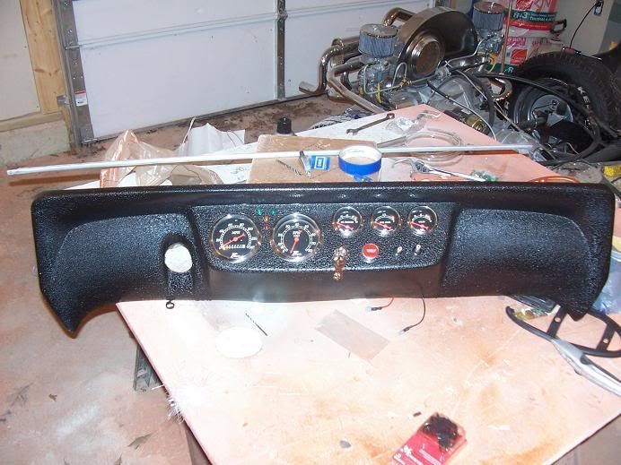
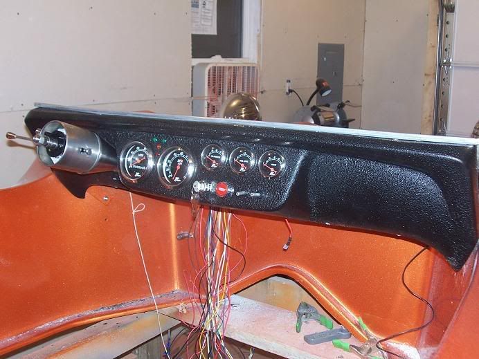
The key is simply used as an "on/off" switch.
Pushbutton start button
First toggle is for headlight on/off
Second toggle is for wiper on/off
Hazard switch is on my titl column.
Let me know if there is anything else.
Jeff
- jspbtown
- Buggyholic
- Posts: 250
- Joined: 26 Wed Dec, 2007 9:57 am
love the layout..
![]() by matter396 » 05 Wed Aug, 2009 2:27 pm
by matter396 » 05 Wed Aug, 2009 2:27 pm
Mike
- matter396
- Buggy Nut
- Posts: 112
- Joined: 03 Sat Jan, 2009 12:01 pm
![]() by jspbtown » 09 Sun Aug, 2009 8:23 pm
by jspbtown » 09 Sun Aug, 2009 8:23 pm
Sure, current cars are a nightmare with electronics, but these buggies are real simple circuits. Nothing complex at all. You will need some special fork connectors. They make two styles....the larger standard ones, and the thinner ones. The standard ones won't fit in the slots.
I was also thinking of using one of these in my current project for the grounds:
http://www.discountmarinesupplies.com/T ... S_BAR.html
It might take some fatter ground supply wires. I never had a problem with what I used before....just thinking if this is worth trying.
- jspbtown
- Buggyholic
- Posts: 250
- Joined: 26 Wed Dec, 2007 9:57 am
![]() by Jack Duncan » 09 Sun Aug, 2009 11:13 pm
by Jack Duncan » 09 Sun Aug, 2009 11:13 pm
CoryN wrote:Cool that's what I got. I was just a little nervous they seemed a little lightweight
Cory, if you think they are a little small, look at the ones from Home Depot. I bought the ones from Radio Shack, but changed to the Home Depot ones that were just a little larger.
-

Jack Duncan - Buggyholic
- Posts: 343
- Joined: 16 Tue Sep, 2008 11:06 pm
- Location: Boerne, TX
![]() by CoryN » 10 Mon Aug, 2009 8:46 am
by CoryN » 10 Mon Aug, 2009 8:46 am
What gauge wire to do that, and how did you feed the power to the fusebox?
- CoryN
- Buggyholic
- Posts: 1108
- Joined: 30 Wed Jan, 2008 12:11 pm
- Location: McKinney, Texas
![]() by jspbtown » 10 Mon Aug, 2009 8:59 am
by jspbtown » 10 Mon Aug, 2009 8:59 am
I "believe" (its been a while) I ran them from directly on the battery or where the battery ground cable attached to the motor/tranny. If I did it from the battery my thinking would be that would be a spot where it would be minimally exposed to corrosive stuff. I don't see a reason to pull it from two different locations.
On my wiring I used the wiring that came with the kit. One wire supplied 1/2 the box with constant on power and I pulled it off the starter lug where the positive battery cabl;e attaches. The other 1/2 of the box was supplied by the ignition switch ("keyed" power). If I had to guess I would say 12 or 10 guage.
- jspbtown
- Buggyholic
- Posts: 250
- Joined: 26 Wed Dec, 2007 9:57 am
![]() by Jack Duncan » 10 Mon Aug, 2009 9:47 am
by Jack Duncan » 10 Mon Aug, 2009 9:47 am
-
Jack Duncan - Buggyholic
- Posts: 343
- Joined: 16 Tue Sep, 2008 11:06 pm
- Location: Boerne, TX
![]() by CoryN » 10 Mon Aug, 2009 10:09 am
by CoryN » 10 Mon Aug, 2009 10:09 am
- CoryN
- Buggyholic
- Posts: 1108
- Joined: 30 Wed Jan, 2008 12:11 pm
- Location: McKinney, Texas
![]() by jspbtown » 10 Mon Aug, 2009 1:05 pm
by jspbtown » 10 Mon Aug, 2009 1:05 pm
Flashers are easy. With a simple 3 wire turn signal (signal coming in wire, right wire, left wire) all you do is bring power to the flasher. Out of flasher to the wire that brings the power into the switch, then right and left wires to your terminal blocks for your signals.
For relays...nice reading here:
http://www.the12volt.com/relays/relays.asp
- jspbtown
- Buggyholic
- Posts: 250
- Joined: 26 Wed Dec, 2007 9:57 am
![]() by CoryN » 24 Mon Aug, 2009 8:31 pm
by CoryN » 24 Mon Aug, 2009 8:31 pm
Question make any sense?
- CoryN
- Buggyholic
- Posts: 1108
- Joined: 30 Wed Jan, 2008 12:11 pm
- Location: McKinney, Texas
![]() by MURZ » 24 Mon Aug, 2009 8:51 pm
by MURZ » 24 Mon Aug, 2009 8:51 pm
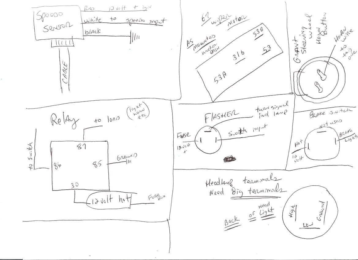
The switch needs a ground, 1 gets power from fuse box, 2 goes to 86 terminal on relay, load ( to lights, wipers, etc) comes out of terminal 87 on relay.
(Just north of where New Orleans used to be)
Dune buggies....Old men have to have something to excercise their minds and bodies
- MURZ
- Buggyholic
- Posts: 342
- Joined: 02 Sun Oct, 2005 10:06 pm
- Location: Madisonville La.
![]() by jspbtown » 25 Tue Aug, 2009 8:24 am
by jspbtown » 25 Tue Aug, 2009 8:24 am
I ran one line to run the relays for all the switches.
Basically power from fuse block to power on the switch, then a jumper to the next, then a jumper to the next (and so on for every switch), then load out to relay, and your ground (again jumpered from switch to switch, then terminal strip).
As an example, I would run my headlight power right from the fuse block to the 30 tab on the relay. And then 1 new line for all the switches to activate the relays. The power to activate a relay is really so very minimal.
- jspbtown
- Buggyholic
- Posts: 250
- Joined: 26 Wed Dec, 2007 9:57 am
![]() by CoryN » 25 Tue Aug, 2009 12:00 pm
by CoryN » 25 Tue Aug, 2009 12:00 pm
I still may ask one more time with the dual pole relay - mine has a little different lay out than the one you describe. I'll have to draw out the diagram for you.
Cory
- CoryN
- Buggyholic
- Posts: 1108
- Joined: 30 Wed Jan, 2008 12:11 pm
- Location: McKinney, Texas

![]() by jspbtown » 25 Tue Aug, 2009 9:13 pm
by jspbtown » 25 Tue Aug, 2009 9:13 pm
If you are using a separate flasher for your flashers then run a non-keyed power to your flasher tab. Then from the other flasher tab run two wires. One to the 5 and one to the 6 tab on the relay.
I am assuming you split the blinkers on your terminal strip. If so, run one wire from the 3 tab of the relay to the right blinker screws, and one from the 4 tab on the relay to the left blinker set of screws.
Working it through:
Power comes into the flasher. The flasher will only flash when there is a load on it. Since 1 & 2 are not connected to anything, and 3 & 4 have no current in them when the coil is not activated, there is no load. Since 3 & 4 are not connected to each other at rest, the normal blinkers work as they should.
When you flip the switch you activate the coil which brings 5 into contact with 3 and 6 into contact with 4. When that happens you now have a load on the flasher so power will go through the flasher, into the relay, and out to the left and right blinkers through tabs 3 & 4. Since the contacts are held together by the switch activating the coil, the flashers will continue to flash until the circuit is broken (and the load removed) by flipping the switch off.
- jspbtown
- Buggyholic
- Posts: 250
- Joined: 26 Wed Dec, 2007 9:57 am
![]() by CoryN » 26 Wed Aug, 2009 10:56 am
by CoryN » 26 Wed Aug, 2009 10:56 am
jspbtown wrote:Another relay if for the wipers. I bring power from the wiper fuse to the 30 tab on the relay. I ground the 85 tab, bring power from my switch to the 86 tab, bring power to the low speed tab on the wiper motor from the 87 tab, and run a wire from the 87a tab on the relay to the auto park on the wiper motor. With this set up you only have one speed, it will auto park, and I get to use a simple toggle switch which I like because you can use the same style switch for everything.
87a tab? Did you run two wires off of the 87 tab? Or is this some different relay with two 87 tabs?
Thanks
Cory
- CoryN
- Buggyholic
- Posts: 1108
- Joined: 30 Wed Jan, 2008 12:11 pm
- Location: McKinney, Texas
![]() by jspbtown » 26 Wed Aug, 2009 11:24 am
by jspbtown » 26 Wed Aug, 2009 11:24 am
http://cgi.ebay.com/12V-DC-30A-40A-Rela ... 286.c0.m14
If you look at the illustration on the relay you will see that the 87a tab makes a circuit when the coil is NOT energized. When the coil is energized the circuit is through the 87 tab.
So...on the VW wiper system you have 4 basic contact points. Ground, low speed, high speed, & auto park.
1. Ground is easy enough. Sometimes this is through the body of the wiper, and sometimes its a tab. Murzi's diagram shows it well...or I have it somewhere if you need it. Let me know.
2. Low speed power comes from the 87 tab on the relay. When the coil is energized power flows through the 30 tab to the 87 tab and the wiper works at slow speed.
3. High speed....I don't hook it up. If your driving and need a high speed wiper then you shouldn't be driving! Most inspection laws just specify an operational wiper....not multiple speeds.
4. auto park....this is the fun stuff. Inside the wiper is a wheel that has a bump in it that disconnects the circuit as it rotates around. The disconnect happens right at the spot to auto park. It prevents it from going around and around.
So what happens is, when you flip your switch, power goes through the 30 tab to the 87 tab. The 87a tab is now a broken circuit. Power is being fed to the low speed tab on the wiper through the 87 tab on the relay. When you shut the switch off you de-energize the 87 tab, but simultaneously you energize the 87a tab. This now takes over and powers the motor. The motor rotates until the wheel inside the motor disconnects the circuit at the right place to park the wipers. Even though 87a still has power going through it, the wiper does not turn because it is internally disconnected. The only time you can get them going again is to energize the 87 tab and have the motor run off the low speed circuit.
Make sense?
- jspbtown
- Buggyholic
- Posts: 250
- Joined: 26 Wed Dec, 2007 9:57 am
![]() by CoryN » 26 Wed Aug, 2009 11:59 am
by CoryN » 26 Wed Aug, 2009 11:59 am
Thanks
- CoryN
- Buggyholic
- Posts: 1108
- Joined: 30 Wed Jan, 2008 12:11 pm
- Location: McKinney, Texas
![]() by jspbtown » 26 Wed Aug, 2009 12:25 pm
by jspbtown » 26 Wed Aug, 2009 12:25 pm
http://cgi.ebay.com/7-refurbished-BOSCH ... 286.c0.m14.
I think I have a couple at home so if you want to PM me your address I will send you one.
- jspbtown
- Buggyholic
- Posts: 250
- Joined: 26 Wed Dec, 2007 9:57 am
![]() by CoryN » 26 Wed Aug, 2009 12:42 pm
by CoryN » 26 Wed Aug, 2009 12:42 pm
In fact I think I'll just use a standard relay for now and get good at timing the off so the wipers are in the right place.
Thanks again for all your help.
- CoryN
- Buggyholic
- Posts: 1108
- Joined: 30 Wed Jan, 2008 12:11 pm
- Location: McKinney, Texas
![]() by Fred » 27 Thu Aug, 2009 8:45 pm
by Fred » 27 Thu Aug, 2009 8:45 pm
- Fred
- Buggy Nut
- Posts: 120
- Joined: 05 Mon Jan, 2009 7:55 pm
- Location: Tyler TX
![]() by jspbtown » 28 Fri Aug, 2009 8:32 am
by jspbtown » 28 Fri Aug, 2009 8:32 am
Power from the fuseblack to one of the two switches on your master cylinder. Murzi's diagram shows which tab is power in and which is power out. The power out to the left rear light, and then daisy chained to the right. Most buggies do not have the brake warning light wired into their system. Its really not needed. So, you use 1 M/C switch, and have the second in there as a back up. Its a simple two wire hook up. Power into the switch and power out to the brake lines.
Now, depending on your rear lights you can have some issues. most stock VW's have two lamps. One is a single filament bulb that is for your blinkers. The other is a dual filament bulb that is for your brake lights and parking lamp.
If you have dual bulbs then the wiring is pretty easy.
If you do not, and only have a single bulb with a dual filament, then you have some options. One is to add a second lamp of similiar design to fnction as a turn signal. The second is to get a trailer converter that are used on.....well...trailers.
These converters basically shut down the appropriate brake light and flash it as a blinker. They are not hard to wire at all. You can probably get them at your local trailer supply place or I can post a link.
- jspbtown
- Buggyholic
- Posts: 250
- Joined: 26 Wed Dec, 2007 9:57 am
![]() by CoryN » 28 Fri Aug, 2009 8:21 pm
by CoryN » 28 Fri Aug, 2009 8:21 pm
- CoryN
- Buggyholic
- Posts: 1108
- Joined: 30 Wed Jan, 2008 12:11 pm
- Location: McKinney, Texas
![]() by jspbtown » 28 Fri Aug, 2009 8:43 pm
by jspbtown » 28 Fri Aug, 2009 8:43 pm
X is power in.
P goes to the dash indicator ( I wouldn't use it....go off your terminal strip to get a right and left signal)
- goes to the switch.
The two you use should be parallel with eachother with the one you don't use going in the opposite direction.
If that fails them go get a two prong flasher.
- jspbtown
- Buggyholic
- Posts: 250
- Joined: 26 Wed Dec, 2007 9:57 am
Who is online
Users browsing this forum: No registered users and 4 guests